HARDWARE
The hardware for your robot is extremely straightforward. First we prepare a few jumpers, then wire up your control board (the Pololu Micro Maestro 6-Channel USB Servo Controller), servo motors, power supply, and computer. Once that’s done, we power up, run a few tests to make sure it’s all working correctly, then start experimenting with Controlling your servos.
You Will Need
- 3x FEETECH Standard Servo FS5103B-FB with Position Feedback
- 1x #1350 Micro Maestro 6-Channel USB Servo Controller (Assembled)
- 2x #3964 Wires with Pre-Crimped Terminals (https://www.pololu.com/product/3964)
- 2x #1900 0.1″ (2.54mm) Crimp Connector Housing: 1×1-Pin
- 1x Battery holder, 4 AA batteries (https://www.pololu.com/product/1159)
- Breadboard (270 point) https://www.pololu.com/product/350
- 1x USB A to Mini cable https://www.pololu.com/product/1315
(All images on this page are courtesy of the vendor website at Pololu.com)
Make Jumpers
- Take out two of the #3964 Wires with Pre-Crimped Terminals (smart kids chose red and black, saving themselves headaches later) and two #1900 Crimp Connector Housings.
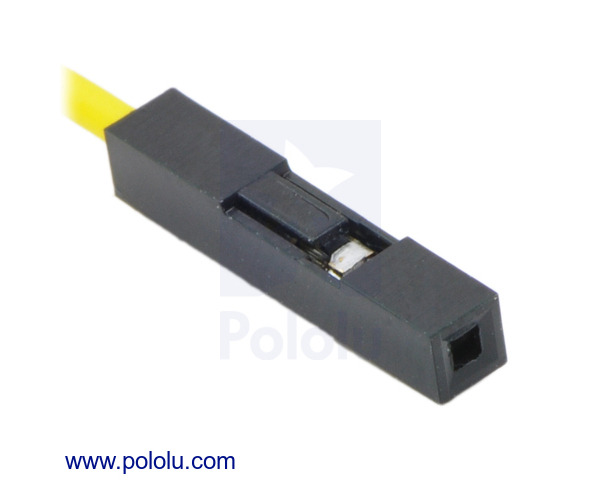
- The crimp connector housings have one side that features a plastic “tongue” and little open window (See Figure 1 below). Hold your crimp connector housing so that the little window is to the right and facing up (as shown in Figure 1).
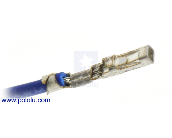
- Look at the female end of your wire. You’ll see that the pre-crimped terminal has one side with two opposing metal tongues on it; you want that side to face up (as in Figure 2)
- Slide the female end of your wire into the left end of the housing, pushing until the female end of the wire bottoms out and clicks into place.
- Give the wire a little tug; it should not slide out easily. If it does, push it back in a littler further this time. Still won’t stay? Rotate wire 90º and try again!
- Repeat with your other wire. You’ll now have two leads, each has one point end, and one plastic-socketed end.
Assemble the Controller and Servos
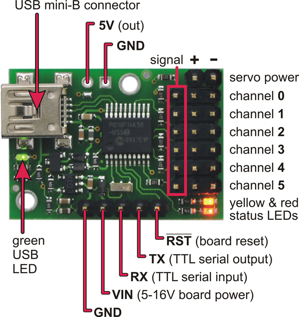
- Get out your Micro Maestro Controller (henceforth “Controller”) and put it on the table with the triple row of pins to the right, the single row along the bottom, and the USB connector to the left. (See Figure 3 for orientation)
- First we plug in power leads:
- plug your BLACK jumper into the pin at the upper right corner of the board (marked with a minus sign (-) in Figure 3)
- plug the RED jumper into the pin immediately to its left (marked with a plus sign (+) in Figure 3)
- Now we plug in servos:
- Note that each servo comes with a pre-wired connector that has white, red, and black leads. Plug your first servo (henceforward “Servo0”) into the pins directly below the power leads. Make sure the BLACK wire on the servo is all the way to the right (it lines up with the BLACK power lead)
- Plug “Servo1” in immediately below Servo0, and “Servo2” below Servo1
- consider labelling each servo (a piece of tape on the plastic housing is fine) to save your sanity later
- Now we’re going to connect the servo power supply. Take our your battery holder, load in fresh batteries, make sure the power is ON, and connect the RED battery lead to the RED power lead on your Controller, and the BLACK battery lead to the BLACK power lead on your Controller.
- You can accomplish this with alligator clips or by twisting the wire from the battery pack around the point on your power lead–but you do have a breadboard handy, so use that:
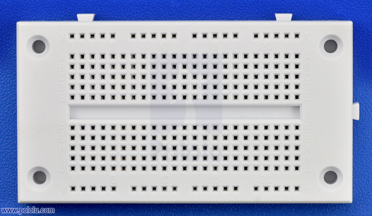
- Place breadboard as shown in Figure 4
- Pick a column of holes. Push the end of your RED battery wire into the first hole in that column, and the end of your RED Controller power lead into the next hole below it.
- Pick a new column of holes. Repeat step #2 with the BLACK wires.
- You’ll know the board is getting power because when you make the final connection all of the servos will jitter a smidge at once.
- You can accomplish this with alligator clips or by twisting the wire from the battery pack around the point on your power lead–but you do have a breadboard handy, so use that:
- Now we connect the Controller to your computer. Plug one end of your USB cable into the Controller and the other into the computer running your Xubuntu Brain-on-a-Stick. This cable also powers the Controller (the battery pack is just for powering the servo motors). Once both ends of the USB cable are plugged in, the green USB LED (left edge of the Controller next to the USB port; see Figure 3) will turn on and stay on. The two indicator LEDs in the lower right corner of the controller (red and yellow; see Figure 3) will light up, and may blink. As long as all three LEDs do something, all is well.
Configure and Test the Controller and Servos
Your computer should be turned on and booted into Xubuntu. If that’s the case, then:
- Launch the Pololu Maestro Control Center software (MCC) by:
- opening the Terminal Emulator
- Navigating to the Maestro folder (probably by running cd ~/Desktop/maestro-linux), typing ./MaestroControlCenter and hitting Enter
- The MCC will open a new window. Go to the “Serial Settings” tab and select “USB Dual Port”
- Go to the “Channel Settings” tab, and change the “MIN” and “MAX” for each of the first three Servo channels (i.e., #0, #1, #2) to the following:
MIN: 600MAX: 2400
- Click the “Apply Settings” button in the lower right to update the Controller firmware. (The button will grey-out and become unclickable once the changes are saved.)
- Go back to the “Status” tab and tick the “Enabled” boxes next to the first three Servo channels listed (i.e., #0, #1, #2)
- Use the sliders next to the check boxes to set servo positions. As you do so the Controller’s green and red LEDs will likely remain on while yellow blinks. Meanwhile, each servo should respond swiftly and smoothly both to the sliders and to changing the value in the “Target” box (values between 992.00 and 2000.00 are valid). When you move the channel 0 slider, only Servo0 should move. Likewise with Servo1 and Servo2 when you adjust channels 1 and 2.
Troubleshooting
Having trouble? Here are a few common issues:
- Doesn’t work at all: Is everything plugged in? Has junk and clutter on your workbench (especially metal bits, like snips of wire or stray screws) created a short circuit by touching any of the components, traces, or pins on the Controller? Is the battery pack power switch turned “ON”? Are you using fresh batteries?
- One (or more) servo works fine, but others don’t respond: Is each servo plugged into the correct row of pins? Is the plug oriented properly (with the black wire lined up beneath the black power lead on the Controller)?
- Extreme “jitter” (twitching and vibrating) or “hunting behavior” (the servo can’t seem to decide where it wants to be): USE BATTERIES TO POWER SERVOS!!! If you have an old or crummy bench supply or wall wart, it may give “dirty power.” This will totally confuse positional servos (which are PWM controlled), causing them to behave irredeemably erratically. Again, make sure you’re using fresh batteries.
- Other erratic behavior: Has workbench clutter created a short circuit? Are you using fresh batteries? Is your USB cable in awful shape? (i.e., been slammed in a drawer, run over in the parking lot, chewed by a pet, etc.)
Further Resources
Polulu (the makers of the Micro Maestro 6-Channel USB Servo Controller and similar gear) has good documentation and helpful tutorials on their website (including this very good video).
Next Steps
If all of the hardware is responding as expected, then it’s time to delve into Control. But before you do so, take a second to relabel those servos as follows:
- Label “Servo0” (the one plugged into channel 0 on the Controller) “headfoot“
- Label “Servo1” (plugged into channel 1 on Controller) “mid“
- Label “Servo2” (plugged into channel 2) “tailfoot“